- Help Center
- Automation/Electrical
- Programmable Relays
-
Pneumatics
- Air Cylinders
- Air Dryers
- Auto Switches
- Boosters
- Electric Actuators
- Fieldbus System/Serial Transmission System
- Fittings
- Modular F.R.L.
- Pressure Switches
- Regulators
- Rotary Actuators
- Solenoid Valve
- Temperature Control Equipment
- Vacuum Equipment
- Photoelectric Sensors
- Process Valves
- Valve Clamps and Accessories
- Pumps
- Additional Articles in Pneumatics
- Safety Valves
- Tubing
-
Hydraulics
-
Automation/Electrical
- Contact Sensors / Liquid Leakage Sensors
- Level Switches
- Basic Switches
- Limit Switches
- Push Buttons / Indicator Lamps
- Thumbwheel Switches
- Safety Limit Switches
- Temperature Controllers
- Counters
- Programmable Relays
- Programmable Controllers
- Safety Sensors
- Safety Door Switches
- Solid-state Relays
- Timers
- Inverters
- Power Supplies
- Axial Fans
- Wiring Systems
- Rotary Encoders
- Pressure Sensors
- Displacement Sensors/Measurement Sensors
- Ultrasonic Sensors
- Emergency Stop Switches
- Power Controllers
- Signal Converters
- Machine Automation Controllers
- RFID Systems
- Measuring / Motor Protective Relays
- Vision Sensors / Machine Vision Systems
- Photomicro Sensors
- Digital Panel Indicators
- Programmable Terminals
- Servomotors / Servo Drivers
- Proximity Sensors
- General Purpose Relays
- Fieldbus Communications
-
Safety
-
Website Help Center
ZEN Programmable Relays: Is the operation of the ZEN and Programmable Controller ladder programs different?
ZEN
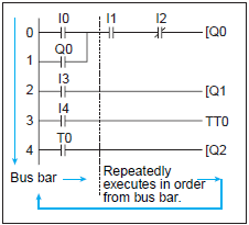
ZEN executes the entire ladder program (up to 96 lines) from the first to last line at one time. Each row is executed in order from left to right starting from the left bus bar.
Reference
- The time from when processing starts at the bus bar until it returns to the bus bar again (to execute the entire ladder program) is called cycle time.
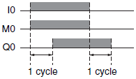
- The ON/OFF status produced by an output contact cannot be used as the input contact status in the same cycle, but it can be used in the next cycle.
The Q0 ON/OFF result is reflected one cycle after MO turns ON or OFF
OMRON Programmable Controllers
Programmable Controllers execute ladder programs one rung (circuit) at a time, starting with the top rung and executing it in order from the left. When the END instruction is reached, the program is executed again from the first rung.
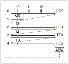
When the following instructions are executed, Q0 turns ON/OFF at the same time as the other bits.