- Help Center
- Automation/Electrical
- Power Controllers
-
Pneumatics
- Air Cylinders
- Air Dryers
- Auto Switches
- Boosters
- Electric Actuators
- Fieldbus System/Serial Transmission System
- Fittings
- Modular F.R.L.
- Pressure Switches
- Regulators
- Rotary Actuators
- Solenoid Valve
- Temperature Control Equipment
- Vacuum Equipment
- Photoelectric Sensors
- Process Valves
- Valve Clamps and Accessories
- Pumps
- Additional Articles in Pneumatics
- Safety Valves
- Tubing
-
Hydraulics
-
Automation/Electrical
- Contact Sensors / Liquid Leakage Sensors
- Level Switches
- Basic Switches
- Limit Switches
- Push Buttons / Indicator Lamps
- Thumbwheel Switches
- Safety Limit Switches
- Temperature Controllers
- Counters
- Programmable Relays
- Programmable Controllers
- Safety Sensors
- Safety Door Switches
- Solid-state Relays
- Timers
- Inverters
- Power Supplies
- Axial Fans
- Wiring Systems
- Rotary Encoders
- Pressure Sensors
- Displacement Sensors/Measurement Sensors
- Ultrasonic Sensors
- Emergency Stop Switches
- Power Controllers
- Signal Converters
- Machine Automation Controllers
- RFID Systems
- Measuring / Motor Protective Relays
- Vision Sensors / Machine Vision Systems
- Photomicro Sensors
- Digital Panel Indicators
- Programmable Terminals
- Servomotors / Servo Drivers
- Proximity Sensors
- General Purpose Relays
- Fieldbus Communications
-
Safety
-
Website Help Center
Which terminals should the G3PX Power Controller inputs be connected to?
It depends on the type of input.
1. Analog Inputs
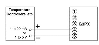
(1) 4 to 20-mA or 1 to 5-V Inputs
Terminals: 4 and 5
Note: The terminals are the same (4 and 5) for both current and voltage inputs.
Input impedance: 250 Ω
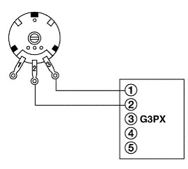
(2) Analog Inputs Using External Main Setting
2. ON/OFF Pulse Inputs
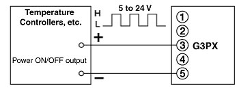
Terminal numbers 3 to 5
(1) Power ON/OFF Pulse Signal Inputs
Example
(2) Contact ON/OFF Pulse Signal Inputs
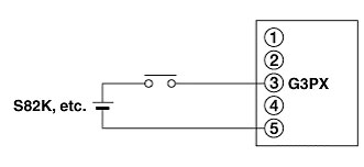
Note: There is only one input of whatever kind. The G3PX may be damaged if there is more than one signal is input.