The D7F-C03 is a Controller with a linear output. Use the following procedure to set it up.
(1) Select the Operating Mode
Set the ACC/VEL Selector to either ACC (acceleration) or VEL (velocity). If you are not sure, set it to ACC.
Acceleration is the change of speed per unit of time. The range of vibration frequencies that can be detected in the ACC mode is broader than in the VEL mode. (The frequency range of ACC mode is 20 to 2,000 Hz.)
The ACC mode is applicable when the vibration frequency is relatively high.
Velocity is the change in distance per unit of time. It is applicable when the vibration frequency is relatively low.
(The frequency range of VEL mode is 10 to 1,000 Hz.)
Depending on the sensing object, the VEL mode may be better than the ACC mode. Try the ACC mode first, but if you encounter many detection errors, set the Controller to VEL mode.
(2) Set the Gain
Set the GAIN Selector in accordance with the level of vibration.
Select a gain from the following three ranges.
The ×10 range is for 9.8 m⁄s2 or lower, and therefore represents a more sensitive setting compared to the ×1 range.
| Range | ACC (acceleration) | VEL (velocity) |
| x 1 | 0 to 98 m/s2 | 0 to 20 mm/s |
| x 5 | 0 to 19.6 m/s2 | 0 to 4 mm/s |
| x 10 | 0 to 9.8 m/s2 | 0 to 2 mm/s |
If the transistor output is used, follow the steps 3 and 4 below.
(3) Set the RUN/SET Selector to SET
The threshold values for ten vibration levels will be displayed on the Level Meter. (These are points where the output turns ON.) Use the threshold adjuster to set the threshold values.
(4) Set the RUN/SET Selector to RUN
The current vibration level out of the 10 possible levels will be displayed on the Level Meter.
If the Level Meter display does not reflect the change in vibration, try switching the operation mode (ACC/VEL) and the gain (range: ×1, ×5, and ×10).
D7F-C03
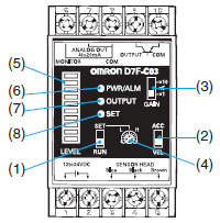
Operations
(1)RUN/SET Selector
The RUN/SET Selector sets the Level Meter indication to RUN or SET.
(2)ACC/VEL Selector
The ACC/VEL Selector sets the operating mode to acceleration or velocity.
(3)GAIN Selector
The GAIN Selector changes the signal strength.
(4)Threshold Adjuster
The Threshold Adjuster sets the threshold value.
Indicators
(5)Level (10 levels)
RUN: Indicates vibration magnitude.
SET: Indicates threshold settings.
| Level Meter levels | Vibration level and threshold settings |
| 10 | 95% or higher FS |
| 9 | 85% to 95% FS |
| 8 | 75% to 85% FS |
| 7 | 65% to 75% FS |
| 6 | 55% to 65% FS |
| 5 | 45% to 55% FS |
| 4 | 35% to 45% FS |
| 3 | 25% to 35% FS |
| 2 | 15% to 25% FS |
| 1 | 5% to 15% FS |
Note: Use the Level Meter indicator strictly as a guideline.
(6)PWR/ALM Indicator
Power ON: Green light
Sensor error: Red light
(7)OUTPUT Indicator
The output transformer operates and the OUTPUT indicator lights at vibration levels exceeding the threshold setting.
The output and indications are the same whether RUN or SET is selected.
(8)SET Indicator
The SET Indicator is lit when SET is selected from the RUN/SET selector.