Using a smoothing capacitor makes the power supply a capacitive load, but as shown in the following figure, the current output is clearly divided between times when hardly any current flows and times when the capacitor is suddenly charged.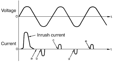
When an attempt is made to turn the Solid-state Relay ON, voltage is applied to the Solid-state Relay, and the Solid-state Relay tries to turn ON, but near point A where there is no current flow the ON status cannot be maintained, so the Solid-state Relay turns OFF and then turns ON when the charge current starts to flow at point B.
Similarly, the Solid-state Relay moves from OFF to ON at point C. If there is a delay in the Solid-state Relay turning ON at point B, the capacitor will no be sufficiently charged, and when the Solid-state Relay turns on at point C it will try to charge the amount insufficient at point B, which will result in a large current flowing. The current is unstable because this process is repeated at points D and E.
As a measure to stabilize the current, connect a bleeder resistor that constantly passes current in parallel with the power supply to keep the Solid-state Relay ON.
| 100 VAC | 5 to 10 kΩ | 3 W |
| 200 VAC | 5 to 10 kΩ | 15 W |