- Help Center
- Automation/Electrical
- Measuring / Motor Protective Relays
-
Pneumatics
- Air Cylinders
- Air Dryers
- Auto Switches
- Boosters
- Electric Actuators
- Fieldbus System/Serial Transmission System
- Fittings
- Modular F.R.L.
- Pressure Switches
- Regulators
- Rotary Actuators
- Solenoid Valve
- Temperature Control Equipment
- Vacuum Equipment
- Photoelectric Sensors
- Process Valves
- Valve Clamps and Accessories
- Pumps
- Additional Articles in Pneumatics
- Safety Valves
- Tubing
-
Hydraulics
-
Automation/Electrical
- Contact Sensors / Liquid Leakage Sensors
- Level Switches
- Basic Switches
- Limit Switches
- Push Buttons / Indicator Lamps
- Thumbwheel Switches
- Safety Limit Switches
- Temperature Controllers
- Counters
- Programmable Relays
- Programmable Controllers
- Safety Sensors
- Safety Door Switches
- Solid-state Relays
- Timers
- Inverters
- Power Supplies
- Axial Fans
- Wiring Systems
- Rotary Encoders
- Pressure Sensors
- Displacement Sensors/Measurement Sensors
- Ultrasonic Sensors
- Emergency Stop Switches
- Power Controllers
- Signal Converters
- Machine Automation Controllers
- RFID Systems
- Measuring / Motor Protective Relays
- Vision Sensors / Machine Vision Systems
- Photomicro Sensors
- Digital Panel Indicators
- Programmable Terminals
- Servomotors / Servo Drivers
- Proximity Sensors
- General Purpose Relays
- Fieldbus Communications
-
Safety
-
Website Help Center
How is an electrical current value of the heater calculated?
The following table shows the different connections possible. The formula under each illustration indicates the electrical current value of the heater elements under normal and abnormal conditions.
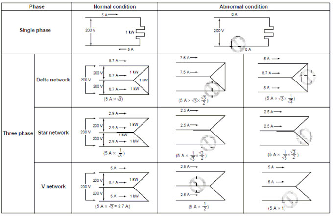
Note: Values in this table are correct when a 200 VAC, 1 kW heater is used on a single-phase or three-phase current.
* Wire electric wires of both terminals to the Heater Element Burnout Detector "K2CU Series" correctly.