- Help Center
- Pneumatics
- Photoelectric Sensors
-
Pneumatics
- Air Cylinders
- Air Dryers
- Auto Switches
- Boosters
- Electric Actuators
- Fieldbus System/Serial Transmission System
- Fittings
- Modular F.R.L.
- Pressure Switches
- Regulators
- Rotary Actuators
- Solenoid Valve
- Temperature Control Equipment
- Vacuum Equipment
- Photoelectric Sensors
- Process Valves
- Valve Clamps and Accessories
- Pumps
- Additional Articles in Pneumatics
- Safety Valves
- Tubing
-
Hydraulics
-
Automation/Electrical
- Contact Sensors / Liquid Leakage Sensors
- Level Switches
- Basic Switches
- Limit Switches
- Push Buttons / Indicator Lamps
- Thumbwheel Switches
- Safety Limit Switches
- Temperature Controllers
- Counters
- Programmable Relays
- Programmable Controllers
- Safety Sensors
- Safety Door Switches
- Solid-state Relays
- Timers
- Inverters
- Power Supplies
- Axial Fans
- Wiring Systems
- Rotary Encoders
- Pressure Sensors
- Displacement Sensors/Measurement Sensors
- Ultrasonic Sensors
- Emergency Stop Switches
- Power Controllers
- Signal Converters
- Machine Automation Controllers
- RFID Systems
- Measuring / Motor Protective Relays
- Vision Sensors / Machine Vision Systems
- Photomicro Sensors
- Digital Panel Indicators
- Programmable Terminals
- Servomotors / Servo Drivers
- Proximity Sensors
- General Purpose Relays
- Fieldbus Communications
-
Safety
-
Website Help Center
How do the indicators on Photoelectric Sensors operate?
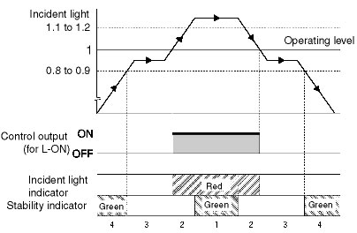
There is a stability indicator (green) and an incident light indicator (red). There are four operation patterns depending on the amount of incident light.
Explanation:
The stability indicator shows the excess gain for temperature, voltage, dust, or other changes in the environment after installation.
Incident Light Indicator
The incident light indicator shows the amount of light entering the receiver.
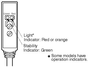
Indicator operation
Note: The operating level is 1.
The following figure shows indicator operation on a graph.